VOGONS


PS/2 Bracket for Asus Motherboard Header

Topic actions

First post, by Artex

User metadata
Rank l33t
Rank
l33t

I saw one post about a 1 x 6 pin (all pins in one row) header & PS/2 bracket that indicated the connector was non-standard. I have an Asus PVI-486SP3 board with a 2 x 4 PS/2 mouse header on the motherboard but I have no bracket. Wondering if this will work..

http://www.startech.com/Cables/Serial-Paralle … Bracket~PLATE6F

Has anyone purchased one of these before, for use with an older motherboard? I know what the pinout should be for both the motherboard and PS/2 connector, but just curious if these 'just work' out of the box without any modification.

My Retro B:\ytes YouTube Channel & Retro Collection
LihnlZ.jpg

Reply 1 of 42, by RacoonRider

User metadata
Rank Oldbie
Rank
Oldbie

Modification is so simple you need not bother.

Reply 2 of 42, by Artex

User metadata
Rank l33t
Rank
l33t
RacoonRider wrote:

Modification is so simple you need not bother.

Is there a guide out there? How do you crack open the black connector to move the wires around?

My Retro B:\ytes YouTube Channel & Retro Collection
LihnlZ.jpg

Reply 3 of 42, by 5u3

User metadata
Rank Oldbie
Rank
Oldbie
Artex wrote:
RacoonRider wrote:

Modification is so simple you need not bother.

Is there a guide out there? How do you crack open the black connector to move the wires around?

No need to crack it open. The wire terminals are held in place with the help of little plastic "tongues" which are part of the connector and can be slightly bent back to release the wire. It is really very straightforward once you look at the connector.

Reply 4 of 42, by Artex

User metadata
Rank l33t
Rank
l33t
5u3 wrote:
Artex wrote:
RacoonRider wrote:

Modification is so simple you need not bother.

Is there a guide out there? How do you crack open the black connector to move the wires around?

No need to crack it open. The wire terminals are held in place with the help of little plastic "tongues" which are part of the connector and can be slightly bent back to release the wire. It is really very straightforward once you look at the connector.

Cool - I'll grab that one then and see how it goes.

My Retro B:\ytes YouTube Channel & Retro Collection
LihnlZ.jpg

Reply 5 of 42, by bestemor

User metadata
Rank Oldbie
Rank
Oldbie

Too bad this one seems like Germany only (and no paypal?)
http://www.ebay.de/itm/221461722240

(for ASUS mobo P55TP4N, but will most likely work on a Asus 486 as well?)

Reply 6 of 42, by vetz

User metadata
Rank l33t
Rank
l33t
bestemor wrote:

Too bad this one seems like Germany only (and no paypal?)
http://www.ebay.de/itm/221461722240

(for ASUS mobo P55TP4N, but will most likely work on a Asus 486 as well?)

They work on all ASUS motherboards (and Aopen) I've tried.

3D Accelerated Games List (Proprietary APIs - No 3DFX/Direct3D)
3D Acceleration Comparison Episodes

Reply 7 of 42, by Artex

User metadata
Rank l33t
Rank
l33t
vetz wrote:
bestemor wrote:

Too bad this one seems like Germany only (and no paypal?)
http://www.ebay.de/itm/221461722240

(for ASUS mobo P55TP4N, but will most likely work on a Asus 486 as well?)

They work on all ASUS motherboards (and Aopen) I've tried.

Are you referring to the one I posted or the one pictured above @ DE eBay?

My Retro B:\ytes YouTube Channel & Retro Collection
LihnlZ.jpg

Reply 9 of 42, by Artex

User metadata
Rank l33t
Rank
l33t

Gotcha. 😀

My Retro B:\ytes YouTube Channel & Retro Collection
LihnlZ.jpg

Reply 10 of 42, by Artex

User metadata
Rank l33t
Rank
l33t

Ok, so I've picked up two of these PS/2 brackets. I have a multimeter (documentation attached) - can anyone instruct on how to do this?

My Retro B:\ytes YouTube Channel & Retro Collection
LihnlZ.jpg

Reply 11 of 42, by Jorpho

User metadata
Rank l33t++
Rank
l33t++

There's not much to say. You have the 2x4 connector, right? All you have to do is remove the pins from the old connector and put them into the new connector. If you know the pinout for the old connector you don't even need the multimeter.

As for removing the pins, it's tough to describe. You'll need to gently poke at the sides of the connector with a needle or other sharp object. As always, you should never apply too much force.

Reply 12 of 42, by schlang

User metadata
Rank Oldbie
Rank
Oldbie

this is from my 486 PVI SP3. hope it helps =)

img_3430p3k1j.jpg
img_3431zqkh9.jpg

PC#1: K6-III+ 400 | 512MB | Geforce4 | Voodoo1 | SB Live | AWE64 | GUS PNP Pro
PC#2: 486DX2-66 | 64MB | Riva128 | AWE64 | GUS PNP | PAS16
PC#3: 386DX-40 | 32MB | CL-GD5434 | SB Pro | GUS MAX | PAS16

Think you know your games music? Show us: viewtopic.php?f=5&t=37532

Reply 13 of 42, by Artex

User metadata
Rank l33t
Rank
l33t
schlang wrote:

this is from my 486 PVI SP3. hope it helps =)

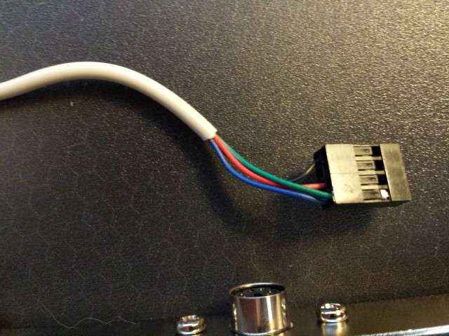
The bracket I picked up has red, green, blue and black wires.

mov8l.jpg

My Retro B:\ytes YouTube Channel & Retro Collection
LihnlZ.jpg

Reply 14 of 42, by Artex

User metadata
Rank l33t
Rank
l33t

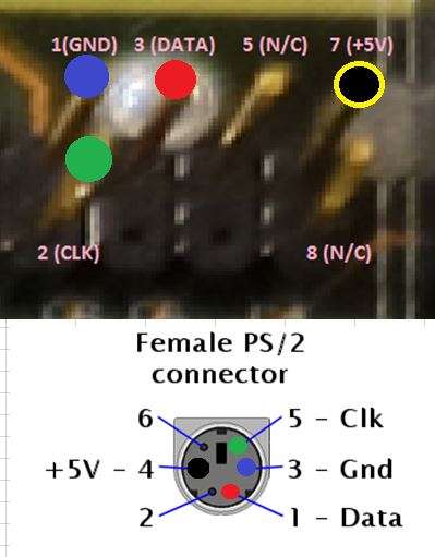
So.. please excuse my novice MS Paint skills. But.. I think I may be ok here. I dug up the pinout for a standard female PS/2 end and the 8-pin header arrangement for Asus Motherboards using this FAQ, and then used my multimeter to test continuity (actually, resistance in Ohms since my multimeter doesn't seem to have a continuity test mode) & color-coordinate the pins/wires of the female end to the metal pins of the connector.

Red->Red (Pin 1 - Data)
Blue->Blue (Pin 3 - Ground)
Black->Black (Pin 4 - +5V)
Green->Green (Pin 5 - Clock)

Does this look right?

7nen.jpg

Last edited by Artex on 2014-06-26, 19:58. Edited 3 times in total.

My Retro B:\ytes YouTube Channel & Retro Collection
LihnlZ.jpg

Reply 15 of 42, by vetz

User metadata
Rank l33t
Rank
l33t

Artex, isnt this another JRTFM case?

http://www.datasheets.pl/motherboards/MOTHERB … ARD_P55TP4N.pdf

Page 19 (#5.2). It's in all relevant ASUS manuals AFAIK (and it's the same pins)

EDIT: Just saw you linked the FAQ, which has the same info.

3D Accelerated Games List (Proprietary APIs - No 3DFX/Direct3D)
3D Acceleration Comparison Episodes

Reply 16 of 42, by schlang

User metadata
Rank Oldbie
Rank
Oldbie

nope, the PVI SP3 manual does not mention the PIN layout.
plug it in and tell us if it works 😁

PC#1: K6-III+ 400 | 512MB | Geforce4 | Voodoo1 | SB Live | AWE64 | GUS PNP Pro
PC#2: 486DX2-66 | 64MB | Riva128 | AWE64 | GUS PNP | PAS16
PC#3: 386DX-40 | 32MB | CL-GD5434 | SB Pro | GUS MAX | PAS16

Think you know your games music? Show us: viewtopic.php?f=5&t=37532

Reply 17 of 42, by Artex

User metadata
Rank l33t
Rank
l33t
vetz wrote:

EDIT: Just saw you linked the FAQ, which has the same info.

So does this look right?

My Retro B:\ytes YouTube Channel & Retro Collection
LihnlZ.jpg

Reply 19 of 42, by Artex

User metadata
Rank l33t
Rank
l33t
vetz wrote:
Artex wrote:
vetz wrote:

EDIT: Just saw you linked the FAQ, which has the same info.

So does this look right?

Yes 😀

Sweet! 😀 Wanted to test since others have complained that they've had to re-wire their connectors.

My Retro B:\ytes YouTube Channel & Retro Collection
LihnlZ.jpg