First post, by keropi
- Rank
- l33t++
Hiya!!
time for Saturday hackery 😁
The target is my beloved IBM PS1/pro pc.
It has 2 things that need attention:
a. noisy PSU fan
b. IDE led is not working with new large HDDs
a.
After 20 years one would expect that the original PSU fan will become noisy. It is a trivial thing to replace it, with a high quality Noctua 80x80mm fan
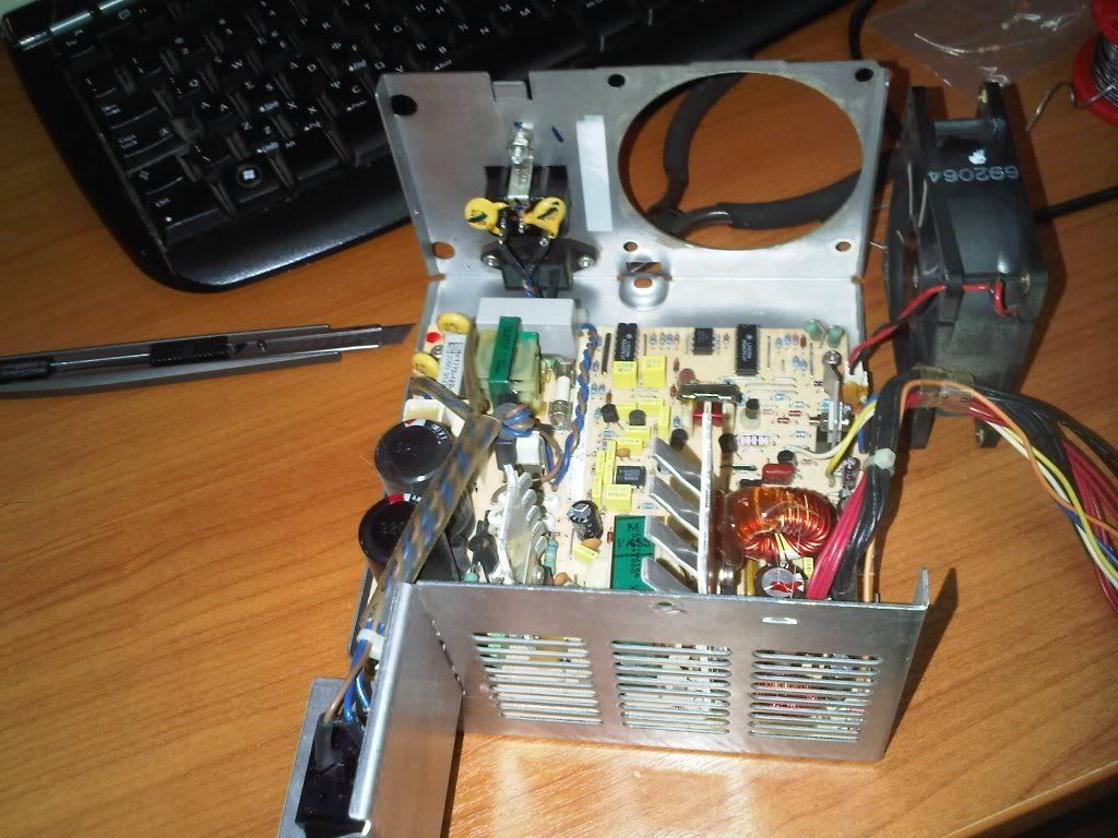
Here is the PSU with the original fan still attached:
and here is the new one screwed in it's place:
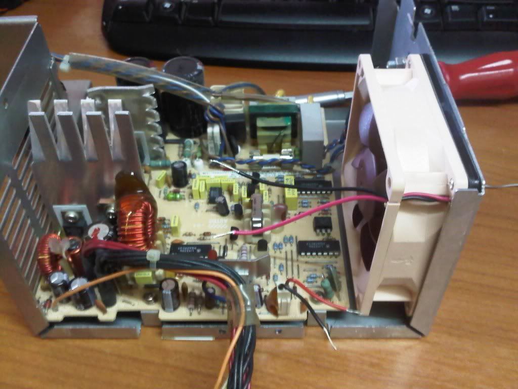
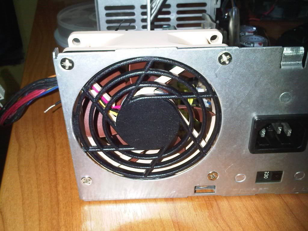
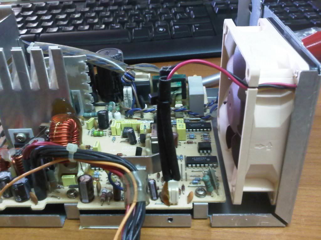
Two soldered wires and some insulation later, and the PSU is once again quiet and with better airflow , win-win 😁
b.
For some reason (probably IBM's strict standards policy) the onboard HDD led does not work with newer and bigger HDDs. It will light up during boot when the BIOS queries the HDD but activity is simply not showing. In all fairness all HDDs up to ~2GBs work fine, it is when you install larger/newer ones (which need a BIOS overlay driver like DiskManager to work) that the onboard led stays off during access.
I was discussing this issue with a friend and he thought if there was a way to grab the activity signal from the IDE cable. That made me remember that Elbox's FastATA (that's a 3rd party IDE controller for the amiga 1200) actually has a small wire that you attach on pin39 of the amiga's IDE header to get the HDD led working 😀 Some googling later I found this web page: http://www.zapwizard.com/oldsite/Guides/IDE/
the job is fairly simply... you disconnect pin39 from the IDE cable and connect it to the shorter leg of a led. Then you grab a +5v signal , put a 150ohm resistor and connect it to the led's longer leg. And presto! you have an independent HDD activity led 😁
I thought I made a small "pcb" that takes a floppy power molex and powers both the HDD led and a small 12v fan I have installed on the 486slc2 cpu upgrade , 2in1 🤣
Let's take a look on the PS1/pro faccia , the led area that interests us for now:
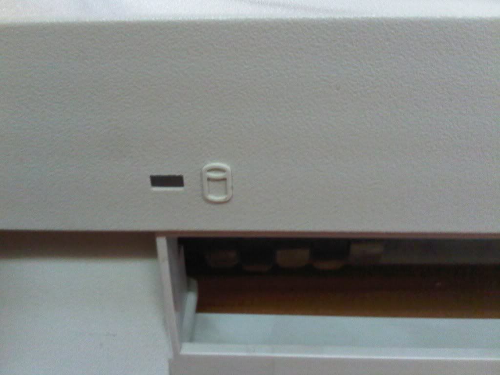
and from behind:
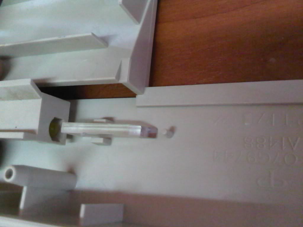
as you can see there is a yellow led on one side of the transparent plastic thingie: the led powers on and the light travels through the transparent part and finally it shows on the front of the pc.
My main goal here is not to butcher the machine and alter it's appearance. It is too precious to me and I already butchered it as a teenager and made a horrible hole in the one and only frontplate cover the machine has so I can have an external IDE cdrom 🙁 , it worked fine but I wish I did not cut the cover plate, you just can't find another 🙁
Anyway, I discovered that if I add the 2nd led in the following place it works fine 😁
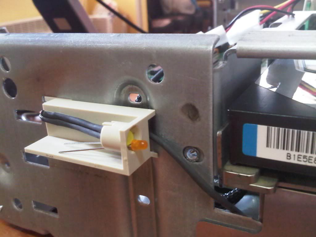
So it is time to get things going!
We begin with the isolation of pin#39 on the ide cable:
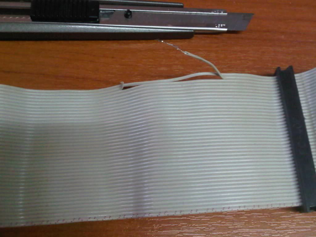
we put that aside and place the connectors and resistor on a piece of development pcb (or whatever this is called)
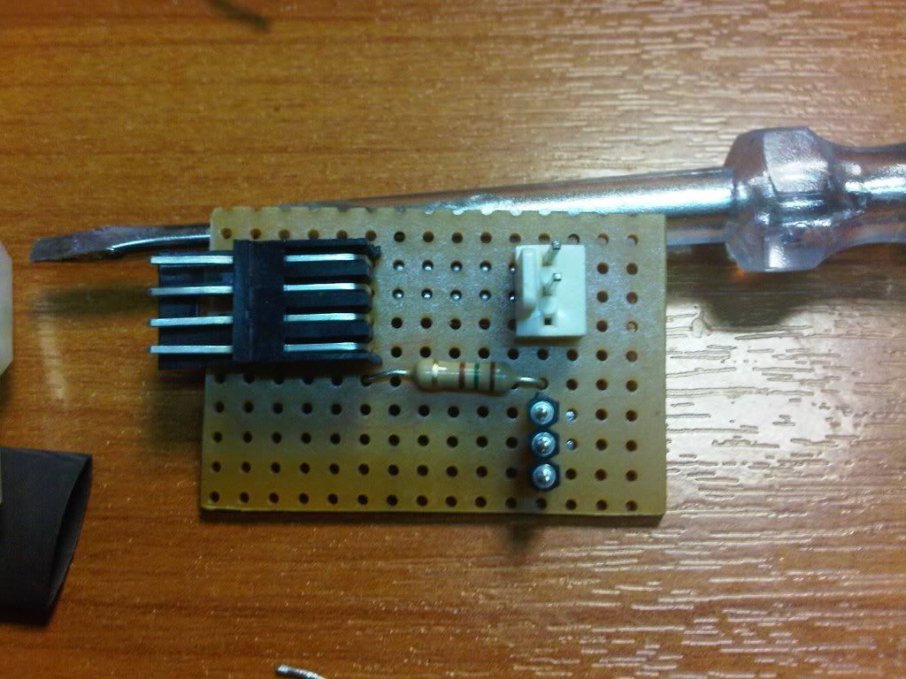
and make solder tracks to connect the parts 🤣
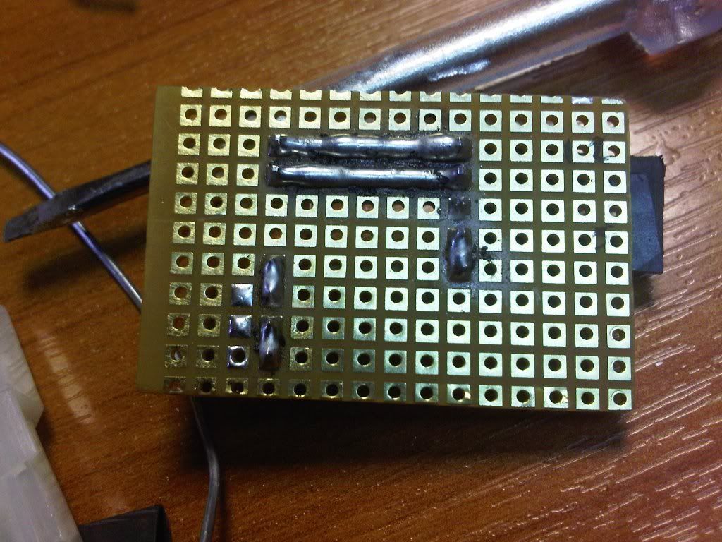
you can see above the 2 straight lines that go to the fan connector (+12v and GND) and the 2 solder joints that connect the +5v power supply to a pin via the resistor.
next it is the led's turn to get connected to the pcb with a 2-wire header (recycled reset cable from a pc case 🤣 )
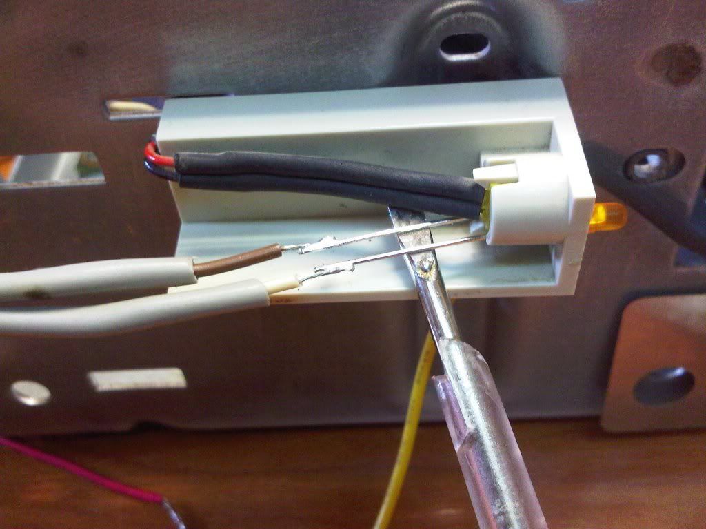
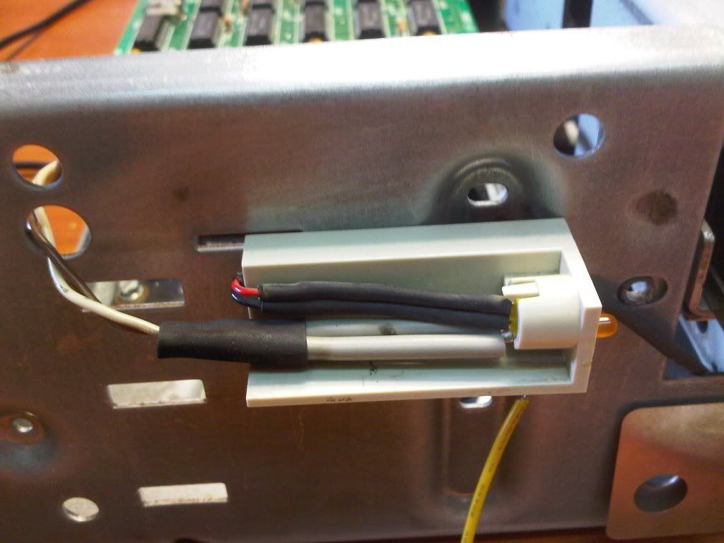
and that's how it looks connected (the led part that is)
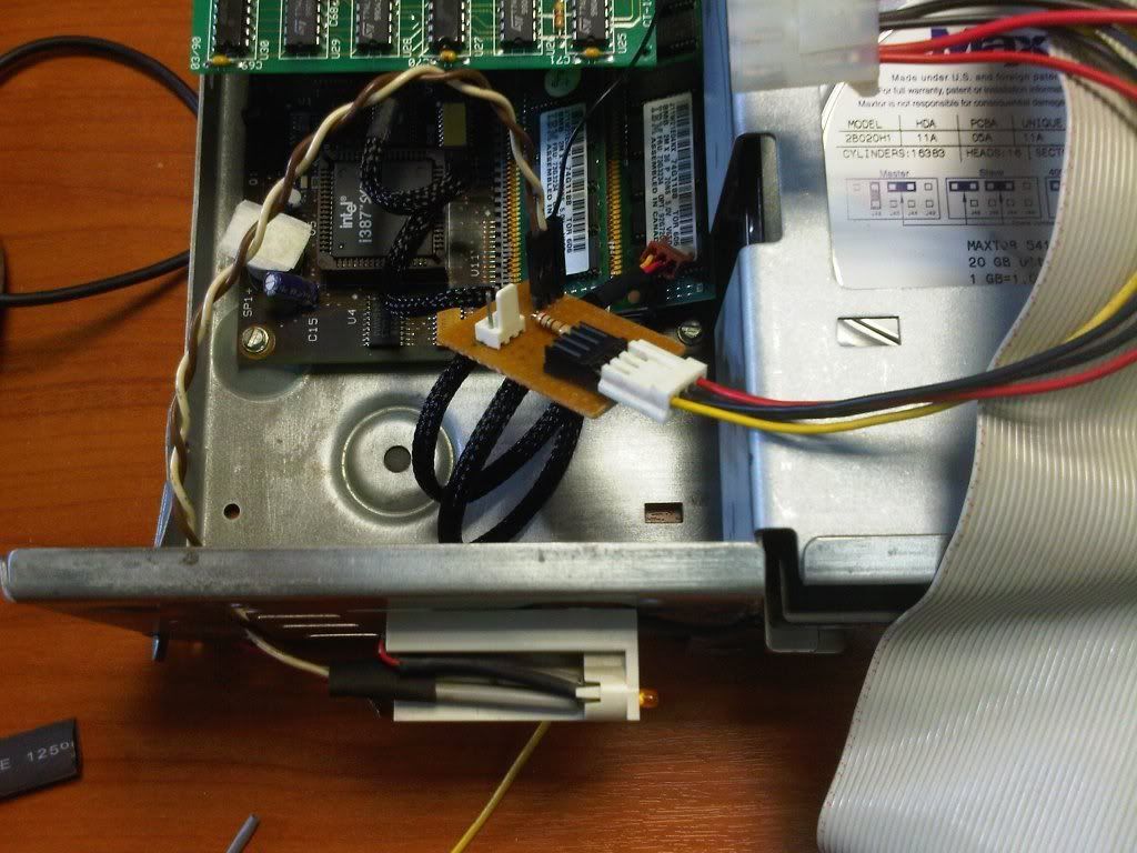
You can see the white/brown wires that come from the led and the single header from the ide cable (a thin black cable)
It works fine 👍 and the HDD activity is finally shown! Plus the fan spins too so it does everything it is supposed to do 🤣:lol::lol:
All that remains is to secure the pcb on some empty space and take a pic of it working 😁


