Reply 140 of 175, by i486_inside
- Rank
- Member
I've replaced a couple ds12887s with new clock chips and it got me thinking more about making permanent replacement chips. I'm almost thinking about buying a bulk quantity of cheap DS12885s in DIP-24 encapsulation from china and making a small cost effective production line of replacement ds12887s.
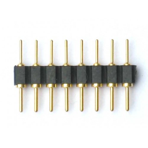
There's a couple things I'm still thinking about though, What would people prefer on battery option, would you prefer a small coin cell on top of the chip, a large cr2 or cr123a holder on top of the chip, or would rather have a pin header so that you can hook up an external 2x(A)AA holder or external lithium battery holder for the size of your choosing.
If you were to use 2xAA or AAA I would recommend using the energizer ultimate lithium or similar lithium iron sulfide batteries since they have a very long shelf life, I think the expiration dates are 20 years from date of manufacture now, which implies very low self discharge, they shouldn't ever leak, and their discharge characteristics make them more suitable for CMOS applications than alkalines because they keep a high voltage above 1.4v for almost all of their capacity where as alkalines have a significant amount of capacity below 1.25V and the minimum Vbat votlage per the DS12885 datasheet is 2.5V.
Still thinking about how to attach the oscillator, there are several way I could do it.
- Use a surface mount oscillator and cut off the bottom of pins 2 and 3 and leave just the wider part of the top of the pins to use a solder pads so that I can mount the oscillator on the side of the chip, I would cut the pins off so that the solder joints are not reheated when it is soldered to a board and so that the solder joints wouldn't be flexed while being inserted into a socket.
- Use a can oscillator and stand it up and glue it to the side of the battery holder for mechanical support then either cut the pins short and solder to the wider part at the top of the pin or I could bend the pins up and solder to them.
- For an external battery header design I could mount a can oscillator to the top of the chip I could either bend the oscillator leads around the side of the chip and use the wide part of the pin as a solder pad or I could bend the ds12885's pins up around the top and leave the oscillator leads straight.
- I could put the chip in a turned pin socket and stand the oscillator up in the larger opening at the top of the turned pins and solder the oscillator and pins 2 and 3 into the socket permanently, then I could wither glue the oscilator to the side of the battery holder or bend it down to glue it to the top of the ds12885.
- Similar to the previous but I could cut pins 2 and 3 short and then use an IC socket to hold the oscillator pins while I solder them to what's left of pins 2 and 3.
- I could bend pins 2 and 3 underneath the IC and mount the oscillator to the under side of the IC which would fit fine in most open frame sockets but wouldn't work in a closed frame socket.
- I could include a socket that isn't permanently attached to the IC and with a turned pin socket I could solder the oscillator to the larger diameter part of pins 2 and 3 and glue the oscillator into the open frame part of the socket, or with a double wipe socket I could bend the pins underneath the socket and solder the oscillator to them then glue the oscillator into the open frame hole for additional mechanical support.
I know this is long and I'm probably putting too much thought into this but right now I am not working and I have way too much time until I have held my learners permit long enough so that I can get a drivers license and go look for a job.

