VOGONS


First post, by IT-Escapee

User metadata
Rank Newbie
Rank
Newbie

Hi Vogons, my name is Shawn and I've been lurking around here (and a few other vintage sites) for a few months since I started putting together an old an old system. It's an AST Advantage! Adventure 575 Plus. I had a similar AST back in 95 and I decided I wanted another one from the era to play all my old games as well as get back into a hobby I have kind of missed for the last few years.

There's a ton of knowledge on these boards and it's allowed me to refresh my knowledge of old hardware pretty quickly, I'm glad there are still people and communities around who help each other out and share what a lot of people have left behind.

So now, on to my dilemma. My AST is one of those old low profile desktops, it has a motherboard that I think were called LPX boards back in the day. Anyway it's basically a 486 board with one EISA slot located in the middle, no ISA or PCI slots on the actual board. The riser card that it came with has 3 ISA slots for expansion. I've seen similar Advantage! Series 486 machines using ISA/PCI riser cards so I looked in the BIOS and confirmed there are configuration options for PCI. I searched around and found an AST EISA riser card with 2 ISA slots and 1 PCI slot. I inserted the new riser along with my new PCI graphics card and excitedly powered on the machine..............and nothing. No BIOS post, no beeps, no keyboard lights and no error messages. The only activity is CPU the fan turns on. Bummer, knew it had to be too easy. I've been searching Google for days but have come up dry as to what could be wrong. I've checked the EISA slot, the pins are all there, the riser card was tested in another computer before I bought it.

I'm wondering since the old riser card was pure ISA is there a jumper somewhere on the mainboard preventing it from recognizing the new riser with the PCI slot? or maybe I'm missing a setting in the BIOS? Is the EISA slot somehow currently configured for only ISA? Unfortunately I was unable to track down the correct manual for the board, it was made by EliteGroup for AST, the EliteGroup model # for the board is UP8810A VIO v3.6, the closest manual I could find was another UP8810 v1 that looks nothing like mine.

Here are some pics of the board and the risers, hopefully its just a jumper setting that's off. If there's anyone who really knows MB jumper identification that can take a look I'd really appreciate some other sets of eyes looking for something I might have missed 😕

The riser card I'm replacing, that's an ESS 1868 sound card built onto the riser. I have an AWE32 that I want to use on the new riser.

WIN_20160216_12_03_49_Pro.jpg
Filename
WIN_20160216_12_03_49_Pro.jpg
File size
2.31 MiB
Views
3072 views
File comment
Old riser I am replacing.
File license
Fair use/fair dealing exception

The card I'm trying to use that's preventing post/boot.

WIN_20160216_12_04_08_Pro.jpg
Filename
WIN_20160216_12_04_08_Pro.jpg
File size
2.42 MiB
Views
3072 views
File comment
New riser preventing post / boot.
File license
Fair use/fair dealing exception

BIOS.

WIN_20160216_10_51_00_Pro (2).jpg
Filename
WIN_20160216_10_51_00_Pro (2).jpg
File size
547 KiB
Views
3072 views
File comment
Bios.
File license
Fair use/fair dealing exception

Current PCI Settings.

WIN_20160216_10_51_13_Pro.jpg
Filename
WIN_20160216_10_51_13_Pro.jpg
File size
642.87 KiB
Views
3072 views
File comment
Current Bios Settings.
File license
Fair use/fair dealing exception

The EISA slot.

WIN_20160216_11_01_42_Pro.jpg
Filename
WIN_20160216_11_01_42_Pro.jpg
File size
374.17 KiB
Views
3072 views
File comment
The EISA slot.
File license
Fair use/fair dealing exception

More pics coming, board close-ups of jumpers.

Last edited by IT-Escapee on 2016-02-17, 02:42. Edited 2 times in total.

Reply 1 of 24, by IT-Escapee

User metadata
Rank Newbie
Rank
Newbie
DSC_0012.JPG
Filename
DSC_0012.JPG
File size
3.52 MiB
Views
3070 views
File comment
Entire board.
File license
Fair use/fair dealing exception
DSC_0013.JPG
Filename
DSC_0013.JPG
File size
3.55 MiB
Views
3070 views
File comment
Close upper left.
File license
Fair use/fair dealing exception
DSC_0017.JPG
Filename
DSC_0017.JPG
File size
3.46 MiB
Views
3070 views
File comment
Close upper right.
File license
Fair use/fair dealing exception
DSC_0019.JPG
Filename
DSC_0019.JPG
File size
3.55 MiB
Views
3070 views
File comment
Close lower right.
File license
Fair use/fair dealing exception
DSC_0020.JPG
Filename
DSC_0020.JPG
File size
3.51 MiB
Views
3070 views
File comment
Close lower left.
File license
Fair use/fair dealing exception

Thanks for looking, am open to any suggestions 😀

Shawn.

Reply 2 of 24, by Kahenraz

User metadata
Rank l33t
Rank
l33t

It looks like there is a special power connector on the 3X ISA riser card. It may be designed to only work when paired with the original system.

It's also possible that the board is expecting a PCI/ISA riser and may think that there is a hardware failure. Hard to tell since a lot of these compact systems were very proprietary at the time.

Be careful with what you plug in there though. Maybe years ago I actually caught fire to a system by misaligning some pins on a ram chip. It caused a dark plume too erupt out of the case and melted parts of the board. The system also was beeping like crazy. I always reimagine it shouting something like, "OMG HELP ME" but with beeps. Good times. 🤣

Maybe it thought the lp0 was on fire?

Reply 3 of 24, by IT-Escapee

User metadata
Rank Newbie
Rank
Newbie

I had to edit my post, the riser picture descriptions were backwards they're fixed now.

But you may be on to something, the old riser has an integrated ESS 1868 sound card (the connectors you noticed) on it, wonder if the mainboard is expecting something the new riser is missing?

Reply 5 of 24, by Kahenraz

User metadata
Rank l33t
Rank
l33t
IT-Escapee wrote:

I had to edit my post, the riser picture descriptions were backwards they're fixed now.

But you may be on to something, the old riser has an integrated ESS 1868 sound card (the connectors you noticed) on it, wonder if the mainboard is expecting something the new riser is missing?

Did you actually use that power connector on the old riser? Also, as it's a different 16/32-bit combo riser, I'm surprised you didn't break something by trying to fit that in there. The height of the connector and the pin layout is completely different. It probably isn't booting booting because the PCI pins are shorting out the ISA pins.

Even though there are similar boards with the PCI slot, you need to first confirm that the chipset supports it. And even then, it may be a bit somewhere in the bios that's set by the manufacturer.

IMO, if you're doing a retro build, the ISA slots are far more valuable. Most of us with PCI slots are all trying to get some kind of ISA compatible mode out of them. The only thing that might work well in there would be a Voodoo accelerator, I guess. Did you have something in mind?

Reply 7 of 24, by IT-Escapee

User metadata
Rank Newbie
Rank
Newbie
Kahenraz wrote:
Did you actually use that power connector on the old riser? Also, as it's a different 16/32-bit combo riser, I'm surprised you d […]
Show full quote
IT-Escapee wrote:

I had to edit my post, the riser picture descriptions were backwards they're fixed now.

But you may be on to something, the old riser has an integrated ESS 1868 sound card (the connectors you noticed) on it, wonder if the mainboard is expecting something the new riser is missing?

Did you actually use that power connector on the old riser? Also, as it's a different 16/32-bit combo riser, I'm surprised you didn't break something by trying to fit that in there. The height of the connector and the pin layout is completely different. It probably isn't booting booting because the PCI pins are shorting out the ISA pins.

Even though there are similar boards with the PCI slot, you need to first confirm that the chipset supports it. And even then, it may be a bit somewhere in the bios that's set by the manufacturer.

IMO, if you're doing a retro build, the ISA slots are far more valuable. Most of us with PCI slots are all trying to get some kind of ISA compatible mode out of them. The only thing that might work well in there would be a Voodoo accelerator, I guess. Did you have something in mind?

Thanks for taking a look.

There was no external power going to the original riser, just a CD audio cable from the CDROM that plugged into the white 4 pin connector. The fitment is perfect, when seated the new riser board is the exact same height as the one I pulled out.

As for the 16/32 bit, I thought EISA slots were designed to handle both 16 and 32, am I mistaken?

Thank you for the chipset advice, my next step should be identifying the chipset and researching the specs. I guess I figured because PCI options were listed in the BIOS already that it was supported but what you said makes me wonder now. I hope those settings aren't hidden away in a locked part of the BIOS if PCI is supported on this board.

My entire goal for the new riser was to use a Voodoo 3 PCI graphics card and my old AWE64 sound card, I've used that combo in the past and it was extremely well rounded when it came to playing games from the late 80's all the way in to the 2000's.

Reply 8 of 24, by Kahenraz

User metadata
Rank l33t
Rank
l33t

I hope you manage to get it working. I had a Voodoo 3 way back and it was a real champ.

If you can't get the riser working with your board you could try finding a board to to go with the riser? Also, see if the BIOS has an option to disable the onboard sound.. unless it's magically connected through the ISA bus or something.

Reply 9 of 24, by DivideByZer0

User metadata
Rank Newbie
Rank
Newbie

Hello, sorry to resurrect this old topic, but I have the same system (an AST Advantage! Adventure 4100, more on that later) and am looking into doing something similar. I've been coming back to this topic quite a bit; the pictures have been a great way to check on things without opening up my case!

I've been doing a lot of research into this PC to try to figure out jumper settings. I was originally only able to find them for an old verision of this motherboard, the 1.1 revision:

https://stason.org/TULARC/pc/motherboards/E/E … 10-8810A-V.html

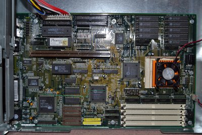
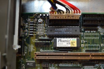
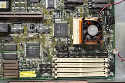
Many of the jumper settings in the above link clearly match up to the jumper settings printed on your and my 1.3 revision motherboards, but with different jumper lablels, and are mostly straightforward but the CPU selection jumpers are much less clear. Here is a picture of the 1.2 revision board, which I don't know of the jumper settings for, but the 1.1 settings above should be more useful for anyone with this board:

Ik1J13N.jpg
Note the different cluster of jumpers next to the CPU, which very roughly correspond to jumpers 19-29 on the 1.3 board.

I was looking at different models of PCs to try to find others with the same motherboard as this one. Since yours is a 575+ and mine is a 4100, I wanted to check if the bioses were the same. Checking the bios update disks whose filenames can be found here http://filedump.glitchwrks.com/mirrors/AST/S-BIOS/bios.txt, for the 575p/575+ (your model, named "twister.bio" in the floppy image) and the 4100 (my model, named "rockyii.bio") are the exact same binary image. So I think it can be concluded that the AST Advantage! Adventure 4100 and the Advantage! Adventure 575 are essentially the same computer with different configurations/marketing. (but, perhaps the bios detects this somehow and changes behavior...)

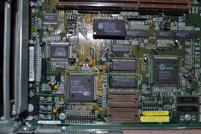
(One other thing I noticed was that patch cable that is on your motherboard is not present on mine. The patch cable seems to end up near the video circuitry, maybe its related to some fuzziness in my VGA output...? I'm considering adding one of these to my board to test this theory)

I also noticed in a hex editor, the bios contains a text string about "Epson 7000". As I'm now learning, Epson ventured into making PCs, and they used this motherboard in a few of the PCs they made. What's more, some seemed to use the exact same case as used for the AST models. Looking for manuals for Epson computers, I was finally able to find one that corresponded to this exact motherboard, including the missing jumper settings*!

Now I can be sure my Pentium Overdrive is configured the right way with the CPU jumper settings 😀 I hope that if you still have this computer, this information will also be helpful to you! (and anyone else googling this) This is the Epson ActionTower 7000/8400, and its spec sheet/short form manual is still available on Epson's website. It has the 1.3 revision motherboard:

https://files.support.epson.com/pdf/apc73_/apc73_pg.pdf

*NOTE: for additional jumper settings not covered in apc73_pg.pdf, see this, "Addendum: Jumper Settings (4100, 575+, and 575)". This is an update bulletin released by AST, and it gives you jumper settings, for Am486DX4 100, and Am5x86 133Mhz: https://web.archive.org/web/19970720031930/ht … ur/3605_001.pdf

Here's a full user's manual which includes the Epson 8400 model, and seems to correspond to this motherboard. I didn't see the CPU jumper settings searching through though, but that's fine, they're in the above two documents. It seems there may be a number of other Epson models using this motherboard. https://files.support.epson.com/pdf/at8k__/at8k__u1.pdf

Also, huge thanks to Epson for keeping these documents online for a 25 year old product category they don't sell anymore! If only all companies did this...

Other models which seem to have the 1.1/1.2 revision of this motherboard using the older jumper settings are the ActionTower 7500 and the Endeavor 486i, as well as earlier versions of the ActionTower 7000/8400, which I also found manuals for. Also of note was this 196 page full users manual for the ActionTower 7500, although it includes the old jumper settings and motherboard layout: https://files.support.epson.com/pdf/at7500/at7500u1.pdf

==============

Now, back to the original topic at hand! I myself have wanted to put a PCI 3d card in this computer. If you look at the first, shorter manual I posted for the ActionTower 7000/8400, it tells you the pinouts for the PCI riser card. The manual even makes reference to a "PCI riser option card". I wasn't able to find any more information about this, but this at least confirms that there should be a card floating around out there that the motherboard (but perhaps not the bios) supports. The manual suggests that it supports 2x PCI and 3x ISA.

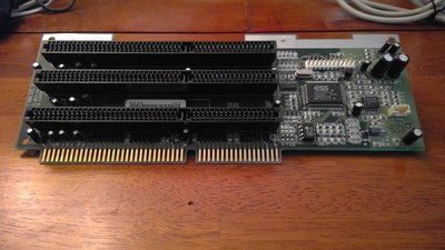
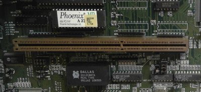
Here's a picture the original riser card to show how deep it goes in the slot. The slot itself is about 1.25cm deep total.
gKLpwRz.jpg

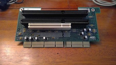
Here's the slot from above.
x3YohwK.jpg
Temporary clock hackjob, please ignore

Some are hard to see, but it has the grooves that line up to the card the OP was trying to use, and opening my case up and counting manually, the pinout appears the same.

I'll be trying to figure this out myself in the next few weeks in terms of finding a working ISA/PCI riser card for this PC so I'll update with any results!

==============

One more very interesting note about this PC: In the manuals for the Epson models, it says you can set this computer into an 8MHz "slow mode" using ctrl + alt + minus and back to normal speed with ctrl+alt+plus. This seems like it would be very cool for ancient software compatibility. I also noticed a turbo switch header (but with no pins), I will probably test that out as well. The manual says "Fast and slow processor speeds available; fast is the speed of the processor and slow is 8 MHz; from the MS-DOS prompt, speed selectable by pressin Ctrl Alt - (slow) or Ctrl Alt + (fast)

I can't actually test this just yet but will see if it works on this model, which brings us to...

ONE MORE very interesting note: I tried using one of those bios flashing disks and copied the bios to the hdd first but it froze at "Waiting..." for quite some time, until I eventually restarted my computer (despite its instructions not to). Well now there's no video and it won't POST, so I have an EEPROM programmer in the mail to recover from that. So I suppose I can't recommend using one of those disks to flash your BIOS (i did copy it to C first but oh well). My bios was from august 1996, the update is from october 1996 and the only changelog information is "ENHANCEMENTS: A Plug-and-Play ID was modified from 81177406 to 1197406. "

Some more digging shows that the AST Adventure 466 uses a bios version "3.6" (the only bios from AST close to 3.7ab) and uses the same hard disk restore disk as the 4100. My guess is that the 466 uses the revision 1.1 or 1.2 motherboard.

==============

Some other stuff:

AST Adventure! User Manual, listed on the AST web site as for the 5166. It seems to mostly correspond to the 4100/575+, but the motherboard picture at the end looks completely different from revs UP8810A 1.1, 1.2 or 1.3. It also doesn't seem to have any CPU jumper settings.
https://web.archive.org/web/19970720031849/ht … ur/3634_001.pdf

By the way, here's a list of AST files and drivers which are not archived, but can be found around the internet
https://web.archive.org/web/19970719190034/ht … pport/files.htm

And it looks like you can find most if not all of that here, obligatory warning about it not being on an official AST site; use at your own risk:
http://filedump.glitchwrks.com/mirrors/AST/

Latest AST BIOS tables:
https://web.archive.org/web/19970719190151/ht … rt/biostbls.htm

575plus video fixup diskette technical bulletin (apparently it adds a couple lines to autoexec.bat)
https://web.archive.org/web/19970720013927/ht … /SBS/0356sb.htm

Last edited by DivideByZer0 on 2020-07-02, 19:39. Edited 2 times in total.

Reply 10 of 24, by DivideByZer0

User metadata
Rank Newbie
Rank
Newbie

I did manage to successfully reflash my BIOS, only to find it was... the same one! Oh well, so much for all that. Also it looks like this "video fixup" I posted just changes a couple lines in autoexec.bat, probably not worth bothering with...

I tried the ctrl + alt + plus and ctrl + alt + minus thing (it only worked with numpad plus and minus). It brought my TopBench score down from 227 to 97. Like the Epson manual said, these keystrokes don't work in protected mode, so I couldn't do it in Windows or in DOS4GW games. However, the setting will stick around if you turn it on beforehand; Doom at max settings was very choppy at the slow speed.

This was also documented in the Phoenix BIOS 4.0 Manual:
https://www.zfmicro.com/library/manuals/Phoen … rev6UserMan.pdf

I also found that shorting the turbo switch pins on the motherboard has the exact same effect and does not stack; i.e., this is just a way of closing the "turbo" switch (thus putting the CPU into slow mode) via keyboard. The restriction to real mode also applies to the turbo switch; shorting the pins has no effect in Windows.

By stopping my Overdrive fan (physically, i think ill only be doing it that way once) to bring the 2.5x Overdrive internal multiplier down to 1x, it brought the speed down even further. Then, by changing jumpers to reduce bus speed, I was able to get it down even more. The lowest TopBench score I saw was around 70, I don't think I tried all 3 at once. It seems like by wiring up a switch to the turbo header, as well as to the bus speed jumpers, and also a switch to break the circuit on the overdrive fan, I could have some decently fine tuned speed control. (although the Overdrive CPU doesn't go back up to full speed if the fan is stopped and restarted) I wonder if having long wires running from the motherboard to external switches could cause problems, though.

Oh yeah, I did find a riser card similar to the one pictured, but no dice; the computer fails to POST, same as OP. I'll have to compare the data sheet on one of these similar cards to see if there are switched pins or something. I tried an ISA-only riser card with 5 slots, and that seemed to work ok as expected (I didn't test it with 5 cards, though)

Reply 11 of 24, by evasive

User metadata
Rank Oldbie
Rank
Oldbie

From the slot it looks like it is wired like a regular ISA slot, not EISA with crossed pins. You'd need to see the bottom of the riser area on the board to see just how many ins are actually in there.

Reply 12 of 24, by Poot36

User metadata
Rank Newbie
Rank
Newbie

Not sure if anyone is still interested but I have managed to figure out about 25% or so of the bottom section of the riser slot that is on my UP8810 VI0/ UP8810A Rev 3.3 motherboard, mainly the power and ground signals. I have labeled the component side A and the solder side B in my diagram with respect to the side of a riser card being plugged into the slot and the pin number is in between the A and B. Pin 1 is nearest the back of the motherboard where the ports are. If someone is interested I will try and fill in as many of the signals as possible. I have also confirmed that the stock ISA riser card is just a extension of the top pins in the riser card slot (as noted by a previous poster). The system will work with out the riser card installed so it is not looking for the sound card.

Gnd A 1 B Gnd
Gnd A 2 B Gnd
INTC# A 3 B INTA#
INTD# A 4 B INTB#
+5V A 5 B +5V
+5V A 6 B +5V
CLK A 7 B RST# -
Gnd A 8 B Grant0
Grant1 A 9 B Request0
Gnd A 10 B Gnd
Request1 A 11 B CLK
- AD 31 A 12 B Gnd
- AD 29 A 13 B AD 30 -
N/C? A 14 B N/C?
N/C? A 15 B N/C?
- AD 27 A 16 B AD 28 -
- AD 25 A 17 B AD 26 -
* C/BE3# A 18 B AD 24 -
- AD 23 A 19 B AD 22 -
- AD 21 A 20 B AD 20 -
- AD 19 A 21 B AD 18 -
N/C? A 22 B N/C?
- AD 20 A 23 B AD 19 (Used for IDSEL (Init Device Select for each PCI slot)) -
- AD 17 A 24 B AD 16 -
- IRDY# A 25 B Frame# *
- DEVSEL# A 26 B C/BE2# *
Lock A 27 B Target Ready *
** PERR# A 28 B STOP# -
SERR# A 29 B N/C (Snoop done on a Pentium class riser)
- AD 15 A 30 B N/C (Snoop backoff on a Pentium class riser)
- AD 14 A 31 B C/BE1# *
- AD 12 A 32 B PAR -
Gnd A 33 B Gnd
Gnd A 34 B Gnd
- AD 10 A 35 B AD 13 -
- AD 8 A 36 B AD 11 -
- AD 7 A 37 B AD 9 -
- AD 5 A 38 B C/BE0# *
- AD 3 A 39 B AD 6 -
- AD 1 A 40 B AD 4 -
- AD 0 A 41 B AD 2 -
+5V A 42 B +5V
+5V A 43 B +5V
Gnd A 44 B Gnd
Gnd A 45 B Gnd

All the pins with a - in front or behind are directly connected to other PCI devices, no buffer or other chips. IDSEL is connected to AD22 for the graphics chip and AD21 for the PCI IDE controller chip. The pins with a * in front or behind have a 33 ohm resistor connected between that pin and the bus and the pin with a ** has a 82 ohm resistor connected to the PCI IDE chip and I am not sure where else it goes (it has a 4.7K ohm pullup to the +5V rail as well). Any of the pins with a ? by them are not connected on this motherboard but on a Pentium class system they are for the 3.3V rail for the PCI slot.

Also found some undocumented FSB selections for the clock chip:
JP 17 1-2, 3-4, 5-6
80 Mhz off, on, on
60 Mhz off, on, off
20 Mhz off, off, off
66 Mhz on, off, on

I have yet to get the board stable at 50 Mhz though.

JP21 pins 2-3 either on or off select the CPU multiplier on compatible CPU's. Do not connect it to pins 1-2 or it will not boot (nothing bad will happen though but I can not verify that for all CPU's). I was using a AMD 5x86 133 Mhz chip and a Intel 486 DX4 chip to test this (did not verify what would happen with incorrect jumper position on the Intel chip). Webpage that I found out what pin on the CPU is for that function: http://web.inter.nl.net/hcc/J.Steunebrink/amd5x86.htm

And here is the partial pinout of the UN9515-01 clock chip (PLL):
Gnd 1 14 10 ohms to +5V (suspect supply rail)
XTL 2 13 JP 17 5-6
XTL 3 12 JP 17 3-4
14.4 Mhz 4 11 JP 17 1-2
24 Mhz 5 10 input? (2V measured when running, turbo switch?)
Pullup to +5V 6 9 +5V (hard wired)
Gnd 7 8 CPU clock out

Last edited by Poot36 on 2022-02-22, 04:13. Edited 11 times in total.

Reply 13 of 24, by Warlord

User metadata
Rank l33t
Rank
l33t

I don't think theres any EISA on those motherboards. There is PCI and ISA only on those motherboards and the EISA looking slot is just wired for ISA. The VGA is on the PCI bus and not sure what else, but there isn't any access to the PCI bus from the riser.

Reply 14 of 24, by Poot36

User metadata
Rank Newbie
Rank
Newbie

@Warlord You are correct that there is no EISA on the motherboard. However I do think that there is PCI on the lower contacts of the riser slot as I was probing some via's that I think were connected to the onboard video card and it beeped on the meter so I would like to think that there is a PCI bus on the connector otherwise why would they use a more expensive connector if they only were going to have ISA? If I can find the data sheet for the video card I would be able to confirm that the via's that I was probing are PCI bus lanes.

Reply 15 of 24, by Poot36

User metadata
Rank Newbie
Rank
Newbie

Well I managed to find the PCI clock on pin B11 between two ground pins so I would say that the bottom set of contacts in the riser slot is a PCI bus. The PCI bus clock comes out of pin 53 on the UM8886 chip (pinout here: download/file.php?id=117812) and goes to pins 2, 3, 4, 5, 6, 7 of the 74F245N octal transceiver chip U27 and comes out on pins 18, 17, 16, 15, 14, 13 of the chip. It then is connected to a 24 ohm resistor and a cap to ground. Pin 16 goes to the video card onboard (Datasheet here: https://ia800603.us.archive.org/12/items/bits … aSheet_text.pdf) and pin 18 goes to pin B11 on the riser slot and pin 17 goes to pin A7 on the riser slot. This confirms that there are only supposed to be 2 PCI slots on the riser card.

Reply 17 of 24, by Poot36

User metadata
Rank Newbie
Rank
Newbie

Well I finally got a riser card from a Packard Bell system (Model KJ012404 P/N: 146230) that has 2 PCI slots and 3 ISA slots and I was able to make it work in the AST motherboard by modifying it. I had the same experience as the first poster where the system would not boot with the unmodified riser in it. I finally figured out that because this card has the 3.3V for the PCB bus wired up to some of the used pins on the AST motherboard it would short out the address bus pins AD19 and AD20 in pin location A 23 and B23 and this is why it would not boot. I covered up the pins with tape as they were already duplicated on pin A 21 for AD19 and pin B20 for AD20 and the system then did boot. However it showed an error in device manager about not being able to assign a IRQ to the card with a Code 29. I finally traced this down to the IDSEL (Init Device Select) pin on the PCI slot being wired on the riser to the incorrect address line resulting in the BIOS being unable to see the card to configure it as the configuration address space was in the wrong location. I finally figured out that on the riser card for the top PCI slot (J2) had IDSEL wired to AD28 and the lower PCI slot (J5) had IDSEL wired to AD30. As these traces were either under the PCI slots or inside the layers of the PCB I decided that the best option of disconnecting them was to fry them with my power supply set at 5V and about 5A of current. I then connected the top PCI slot to AD20 and the lower PCI slot to AD19 and then the error message in the device manager went away and I was able to use both PCI slots. I think the orignal riser for this motherboard would have used the pins at locaton 23A and B for setting the IDSEL for the PCI slots and that is why you can not place a generic PCI ISA riser card into this motherboard. I hope this helps anyone who wants to make a riser card for this system.

Reply 18 of 24, by Poot36

User metadata
Rank Newbie
Rank
Newbie

By the way I can not get this system stable at 50Mhz FSB no matter what I do. Could it be that the very limited BIOS is somehow causing it? I have tested the CPU in another motherboard and have confirmed that it will run stable at 50Mhz FSB and that the ram is 60ns and the cache is 15ns. Could the onboard IDE controller made by CMD model PCI0640B be the issue? I have disabled the onboard VGA and it does not make any difference.

Reply 19 of 24, by darry

User metadata
Rank l33t++
Rank
l33t++
Poot36 wrote on 2022-02-22, 04:19:

By the way I can not get this system stable at 50Mhz FSB no matter what I do. Could it be that the very limited BIOS is somehow causing it? I have tested the CPU in another motherboard and have confirmed that it will run stable at 50Mhz FSB and that the ram is 60ns and the cache is 15ns. Could the onboard IDE controller made by CMD model PCI0640B be the issue? I have disabled the onboard VGA and it does not make any difference.

I should be getting my hands on a 575 Plus soon . Looking forward to see what it can do (I have not owned a socket 3 system since 1997). Running the CPUS base clock at 50MHz probably implies running the PCI bus at 50MHz, which probably doesn't help . Also the CMD640 is not all that reliable to begin with :

https://web.archive.org/web/20010609190128/ht … z1000/index.htm

# Linux centered, but issue is not Linux specific
https://www.kernel.org/doc/Documentation/ide/ide.txt

EDIT :
That Dallas clock chip looks soldered. I'm either going to have to unsolder it and solder in a socket (I have a replacement from Glitchworks) OR buy a dremel . Somehow, getting a dremel and going to town on the existing chip appeals to me .